Mental calculation of decibel

The decibel (dB) is widely used in electronics to describe ratios. Many people find this logarithmic unit difficult to understand, but in fact, it was designed for mental calculation and should not be perceived as overly complicated.

dB is suitable for situations where the dynamic range is large but the requirement for significant digits is not high. For example, whether the exact value of ripple rejection ratio is ten thousand times (80 dB) or fifteen thousand times (83 dB) is not particularly important; it is sufficient to know that it is not one thousand times (60 dB).

Read more...

Marking Codes for E96 0603 Resistors

The most common marking system for chip resistors is the three/four-digit marking system, where the first two/three digits are the significant figures, and the last digit is the order of magnitude (in ohms, indicating the number of zeros added after the significant figures). For resistors less than 10 Ω or 100 Ω, the decimal point is represented by the letter R. For example:

Marking 1 Marking 2 Value
681 6800 680 Ω
914 9103 910 kΩ
R01 010, R010 10 mΩ
6R8 6R80 6.8 Ω

Due to the limited printable area on 0603 chip resistors (0402 and smaller packages generally have no markings), some E96 (1%) 0603 chip resistors use the two-digit plus one-letter marking method described below to save one character. This method is also known as the EIA-96 SMD Resistor Code.

Read more...

I/Q Imbalance Correction

Problem

Calculate

\[ \begin{align*} I(t)= & A \cos\omega t, \\ Q(t)= & A \sin \omega t \\ \end{align*} \]

from acquired signal

\[ \begin{align*} I_0(t)= & A \alpha \cos \omega t, \\ Q_0(t)= & A \sin(\omega t+\psi). \end{align*} \]

Equations

From

\[\sin(\omega t + \psi)=\sin \omega t \cos\psi+\cos \omega t \sin\psi\]

we have

\[\begin{pmatrix}I_0(t) \\ Q_0(t)\end{pmatrix} = \begin{pmatrix}\alpha & 0 \\ \sin \psi & \cos \psi\end{pmatrix} \begin{pmatrix}I(t) \\ Q(t)\end{pmatrix} ; \]

I(t) and Q(t) can be obtained by matrix inversion:

Read more...

Some experiments on My4TH (4): Peripherals

EEPROM Card and Backplane

EEPROM Card

For EEPROM cards, firmware provided on this website arranges adjacent blocks on the same EEPROM chip, with block numbers ordered according to EEPROM addresses.

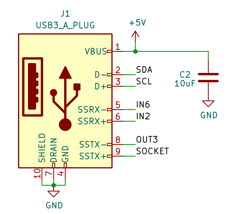
The EEPROM card card uses a USB 3.0 Type-A interface, where the power contacts are compatible with standard USB interfaces, and the signal contacts are used for I2C interface and addressing:

EEPROM Card Interface

SOCKET connects to EEPROM address line A1

Read more...

Some experiments on My4TH (3): Faster speed

Working at 20MHz and 22.1184MHz

Tests have shown that My4TH can operate stably at 20MHz (using the 10MHz ROM image file provided by the original author at baud rate 9600) by increasing Vcc to 5.2V with 74HC series logic circuits and AM27H256-45/35DC.

This configuation can work at 22.1184MHz with Vcc=5.4V:

U2 U3 U4 U9 U15 U16 Others
74F161A(TI)/ 74AC161(TI) 74LVC541A(TI) 74ACT08/ 74LVC08 AM27H256-45/35DC (needs to be selected) IS61C256AL-12T(L)I/ CY7C199(L)-15ZC 74HC series

Higher baud rate

By adjusting the delays in serial subroutines, the system can operate at 14400 baud above 16MHz and 19200 at 22.1184MHz.

Read more...

Some experiments on My4TH (2): Playing music

In the 1960s and 1970s, Broadcast radio receiver was an essential tool for debugging computer memory. Users could use an ordinary broadcast radio to monitor the electromagnetic radiation emitted by the computer, confirming the operational status of magnetic core memory and the bus. Users quickly discovered that this phenomenon could be used to play music (e.g. here and here).

While My4TH utilizes modern EPROM and SRAM, its bus still generates some electromagnetic radiation. Experiments have shown that a regular AM radio can pick up the electromagnetic radiation caused by status changes in the bus.

Read more...

Some experiments on My4TH (1): Running at 16MHz

My4TH is a minimalist computer designed by Dennis Kuschel. This computer is extremely simplified in its design, employing a serial ALU and utilizing 16 74HC series CMOS logic devices along with microcodes from ROM for CPU. It runs the Forth system. Here are some experiments related to this computer.

Increasing the running speed

To ensure the state of the bus during reset, the original version of My4TH employs 10k resistors to pull down the data bus to GND. This introduces compatibility issues between TTL and HCMOS voltage levels: the outputs of RAM 62256 and ROM 27C256 conform to TTL levels, with a minimum high-level output voltage (\(V_\mathrm{OH}\)) of 2.4V; whereas the minimum high-level input voltage (\(V_\mathrm{IH}\)) for 74HC devices is \(0.7 V_\mathrm{cc}\), which is 3.5 V when powered at 5 V.

Read more...

A Wheatstone bridge regenerative (WBR) receiver with 2N7002

Basic principles

The circuit is based on the N1BYT’s WBR receiver, as shown in the schematic below. Q1 is the core of a Colpitts oscillator circuit, and RV2 and RV5 adjust whether the circuit oscillates (i.e., regeneration strength). L2, C7, C8, and six diodes D1 to D6 form the oscillation tank circuit. The input signal is attenuated by RV1, and then fed into the middle tap of L2 with L1. The DC path of the variable capacitance diode anode is provided by L1.

Read more...
1 of 1